Terry Hendricks Phd. : Surfboard
Hydronamics Part 2.
Surfer Volume 10 Number 1, March 1969.
Introduction
This article has been reproduced, with
considerable difficulty, simply because discussions of
surfboard dynamics are exceedingly rare.
Unfortunately, the illustrations and
graphs are poorly reproduced.
It would be disingenuous to critique Hendrick's work without
access to Part One, and the subsequent Part Three.
However, I find this analysis mystifying, and I am tempted
to suggest it is misleading; perhaps even wrong. Page
84
Surfboard
Hydronamics Part II.
Terry Hendricks Phd.
Back at Pipeline: perfect
peeling lefts, and this time you're prepared. You've cleaned the scabs of wax off the bottom of
your board and line-sanded it to further reduce skin
friction drag. You take off on your round-bottom, high-rail
surfboard, and knife across the stick wall. White water explosion, and you're nailed just short of
making the wave. The wind has picked up by the time you reach shore,
and there is a little chop on the wave surface. You pick up your flat, rockerless, dropped-rail model
and paddle back out, hoping for more speed. Your board skips, hitting the high spots, and you
shift your weight back slightly to regain control. But you've lost your speed, and it's suck, throw,
pound and swim. You've just taken two wipeouts that might have been
avoided had you reversed the order of your surfboard
selection.
In Part 1: Drag, the difference between laminar and
turbulent flow was discussed, and comparisons of skin
friction drag for several surfaces were made. In contrast to friction drag- which is relatively
insensitive to the shape of the board-
pressure, wave and spray drag result from the variations
in pressure over the board's surface; and this, in turn,
is dependent on shape. Calculation of the pressure distribution is greatly
complicate it by the fact that the board is at the interface
of two fluids- air and water- of vastly different viscosity
and density. Although it is usually necessary to use model [or full
scale] tests to obtain quantitative results, qualitative
features of the flow (and hence drag) can be obtained from
basic hydrodynamics. The weight of the surfer and the hoard is
supported by two types of lift forces- buoyant lift
(resulting from the displacement of waer) and dynamic lift
(resulting from pressures generated by the passage of
water under the board. As the speed of the board increases above 4-6 mph.
pressure forces are generated which cause the board to rise
part way out of the water. For velocities greater than about 7-8 mph. this dynamic
lift is the primary means of support, and the board is said
to be planing. Since the friction drag is dependent on the netted area
the friction drag is reduced as the board rises. For planing watercraft, the most desirable trim angle is a compromise
between minimizing the friction drag and reducing the drag
produced by generating dynamic lift (figure 3).
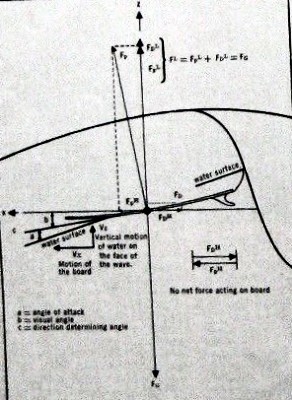
The angle commonly, but erroneously, referred to as the
trim angle is the angle that the board makes with a
horizontal line (angle "b" in Figure 1a). Henceforth, we shall refer to it as the visual angle. In order to generate dynamic lift, the bottom surface
of the board must make an angle with respect to the surface
of the water (angle "a"). This occurs as the tail of the board is depressed below
the surface of the water. This angle is referred to as the "angle of attack" or
"trim angle," and determines the relative amounts of
friction and pressure induced drag. Angle "c" is the direction determining angle. In the case of Figure 1a decreasing this angle will
cause the board to rise in the wave; conversely, increasing
the angle will cause the board to move toward the bottom. In our illustration, angle "c" is such that the board
maintains the same position on the wave. There are three basic forces acting on
the surfboard: 1. Fg. the force of gravity. 2. Fp. the pressure
forces (acting perpendicular to the face of the board).
Figure
1a
Figure
1b
Page 85
3. Fd. the drag forces
resulting from skin friction, the drag of the fin, and
from separated flow.
These act along the direction of the board.
Each of these forces can be broken down into a vertical
and horizontal component (Fg has only a vertical
component) and are labelled Fpv, Fph, Fdv, and Fdh
respectively. Let us assume that the board is at
equilibrium: that is, it is not accelerating or
decelerating, but is moving at a steady rate of speed.
From Newton's Laws of Motion the sum of the vertical
forces must equal zero, and the sum of the horizontal
forces must equal zero.
The forces on this figure have been chosen so that this is
true.
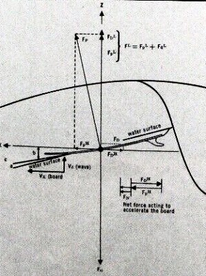
For a given surfboard design, the dynamic lift is
approximately proportional to the angle of attack; as the
angle of attack increases, the dynamic lift increases.
Let us see what would happen if we could design a board
which would produce the same dynamic lift as the Board of
Figure 1a, but at a smaller angle of attack. Furthermore,
let us assume that the board is traveling with the same
speed and direction on the wave (hence angle c and the drag force, Fd are the same
as in Figure 1a).
The resultant set of forces is shown in Figure 1b.
It is now evident, however, that Fph is no longer equal to
Fdh, so that there is a net force, Fh, acting to
accelerate the board to a higher speed. Therefore, if maximum speed is desired, it is clear
that it is desirable to produce a given
dynamic lift for the smallest angle of attack. For instance, it can be shown that a board with
considerable rocker requires a greater angle of attack
for the same dynamic lift as a flatter board, and
hence will be slower.
If the wetted area of the board is roughly constant, the
dynamic lift will be a maximum (for a fixed angle of
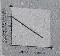
attack) if the average pressure is maximised. Measurements have been made of the lift produced by
planing surfaces with varying amounts of dihedral (or
"V") and it has been found that increasing the "V"
decreases the lift that is generated (the "V" keeps
the board in the water).
Figure
2 gives a typical curve for the liftgenerated by a V-bottom
planing surface (in terms of the lift generated by a flat
surface) for various dihedral angles. In the forward and middle portion of the.
board, only one side is in contact with the water, and "V"
would have less effect on the lift than at the rear of the
board where the entire bottom is in contact. In some circumstances, "V"
in the middle might even reduce the skin friction drag.
Near the rear, however, the curve of Figure 2 gives an
indication of loss of lift associated with "V"
drag.
This loss of lift results, in part, from lateral flow
across the board, the center of the wetted area of a
board must be a region of high pressure in order to produce
dynamic lit!; however, at the rails, the pressure is equal
to one atmosphere, thus serving as a low pressure area. Narrow planing areas, or "V" or
roundness, tend to promote lateral flow from the high to the
low pressure areas, thereby reducing the average pressure. For "round bottom" boards this flow is over a curved
surface, so that the pressure is reduced more than
for a flat surface (remember the effect of rocker). Round rails have the same general effect on the lift
as round bottoms, and are particularly detrimental to
speed when on the rear portion of the board (more an this
in Part III). In addition to reducing the lilt, the water
tends to remain attached to the board (Coanda Effect)
increasing the wetted area and
the skin friction drag.
From the results of Figure 1a, 1b, it would seem desirable
to reduce the angle of attack to zero and rely entirely on
buoyant lift (and a larger board), since this would
eliminate the induced drag associated with dynamic lift. From practical experience, this is clearly not
the case. The reason is our old enemy, friction drag since the
wetted area is much larger
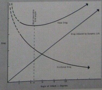
when the board is supported by buoyant lift. Fig. 3 shows a typical drag curve (for a fixed board
speed)as a function of the angle of attack. Minimum speed for hard edge ("dropped" rails") planing
craft generally occurs between three and five degrees. From the diagram, it is clear why nose riding (angle of
attack near 0"), is not as fast as moving sightly
back on the board. It is also clear that "stalling" is associated with
greater induced drag (even though the friction drag is
decreased). The obvious, but generally erroneous, conclusion is
that a board should have little rocker, a flat bottom and
"knife sharp" dropped rails. What we have neglected to consider is the stability and
turning of such a board. If a board is flat and almost completely supported by
dynamic lift then any ripple or chop may cause the board to
leave the water. Similarly, if the surfer's weight is suddenly shifted
back - perhaps to stall - the board may "porpoise". The effect this can have on control is easily
imagined. A board that has a somewhat larger percentage of
buoyant lilt may go through the same chop with considerably
less effect. Except for nose riding, where large dynamic lift is
required at the the front of the board, it would seem
desirable to have some degree of "V," or roundness, since
this portion is generally out of the water when in trim,
and would not generate as much lift as a flat surface when
hitting chop. The effect of rail shape on turning and drag will be
discussed further in the next article. Also to be discussed are fin design, the influence of
"kick" in the rear portion of the board, and some
considerations on plan form.